Nerf Sentry Turret

The goal of our project was to design an automated Nerf turret which would be capable of identifying and tracking targets. Originally we planned to use an image sensor which would be able to identify and track a certain color. However due primarily to optics issues we were unable to interface the image sensor with our design and instead used an ultrasonic range sensor to identify targets. The turret was able to pan laterally and fire automatically from a clip of 10 darts. It supported three operational modes: manual (full user control), semi-automatic (automated target identification with user authorization for firing), and fully automatic (automated target identification and elimination).
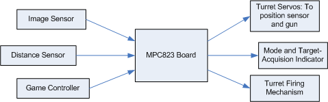
From a high level design perspective our final Nerf turret had two primary input devices: a game controller - which allowed the user to move the turret, fire the gun, and change the operating mode - and a distance sensor which was used to identify new targets that had entered the field of view. This input information was processed and then would be used to the turret if necessary, notify the user of the current mode, and, if a target had been identified, fire the turret. The general control algorithm for the distance sensor was to scan the room to create a rough "map" of the stationary objects. Once this map was created the turret identified targets by observing changes between the current distance sensed and the stored "map" value. If this distance was shorter than the stored value the turret recognized the new object as a target, and would proceed to identify the boundaries of the object, and finally shoot the middle of the target.
Although the image sensor was not implemented into the final design from a high-level, we implemented an algorithm to process the pixels on the fly. First we divided the image into different segments which would each be assigned a color score. Then, as each of the pixels coming from the image sensor corresponded to a different color, we would add or subtract the brightness value of each pixel from the score of the segment containing that pixel. This allowed us to identify the segment with the highest concentration of a certain color which, in theory, would allow us to then track a target of that color.
We worked together on many, if not most, of the tasks for our projects ("extreme programming" style). These included:
Tasks completed primarily by Adam included:
Tasks completed primarily by Paul included:
 |
 |
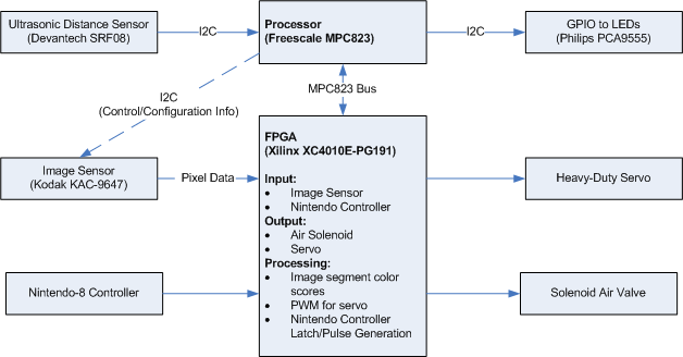
The image sensor had two different bus interfaces that we had to use. The first was an I2C bus which was used to send control signals to the image sensor - the most important of which were to set a configuration register to switch the device to "master mode" (so it would generate its own VSYNC and HSYNC signals), and to change the active window size.
Once the device was configured properly it sent data over a 13 bit data bus (containing a 10-bit brightness value for each pixel, a pixel clock, and horizontal and vertical sync signals). The image sensor also required a master clock signal - we gave it a 10 MHZ signal by dividing the MPC823's bus clock in half. The pixels were arranged in a so-called "Bayer Pattern" where each pixel was filtered to represent a single color.
Our goal was to identify a red-colored target. Most of our image-processing logic to accomplish this was in the FPGA, as the processor had no possibility of handling the amount of data provided by the sensor. The processing proceeded roughly as follows: first, the image was divided vertically into 8 segments. Whenever a new pixel value in was read, it would either be added (if it was a red pixel), or divided by some factor and subtracted (if it was a blue or green pixel) from a running sum for the appropriate segment. Once an entire frame had been processed (as indicated by the VSYNC signal), the final sums would then be stored in a register, and an interrupt would be generated, so that the processor could read these values. The sums represented a "score" for each segment; the segment with the highest value would be the one with the highest concentration of the color red (presumably, the target).

The ultrasonic distance sensor communicated entirely over the I2C bus. Operation was relatively simple: to initiate a ranging, a command would be written to a certain register; 65ms later, the resulting range value could be retrieved by reading two registers and concatenating their contents.
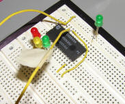
The GPIO also communicated over the I2C bus; we initially used it to test our ability to communicate with I2C devices by means of the MPC823's onboard I2C controller. After this initial testing was successful, we made use of the GPIO to notify the user of the current mode of the turret and to notify the user when a target had been identified. In order to provide this information to the user we used four leds: three that identified the mode, and one which identified when a target had been detected.
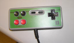
In order to interface to the Nintendo controller we had to generate the proper "latch" and "pulse" signals. To do so, we used a hardware timer to divide the clock to have a 12ns period. A counter then caused the "latch" signal to be asserted at the appropriate interval; in asserting "latch" it also activated a finite-state machine which enabled the generation of the "pulse" signal, and enabled a shift register to read all of the button values at the appropriate times.
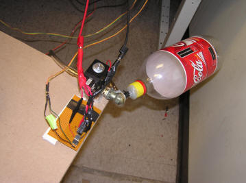
To control the solenoid we mapped a 1-bit writable register to one of the test points. This allowed us to turn on and off the solenoid with a write in software. The more complicated part of the solenoid interface was the current buffering required to power the 15W, 12V solenoid. Thankfully a past project had used this solenoid before and had already designed the hardware required. Nevertheless we spent time to understand the circuit and verify its operation: In order to prevent the massive current draw that the solenoid generated when it was triggered its power circuitry was isolated from the rest of our design. This was done using an optical isolator, which separated our control signal on the I/O board from the signal used to switch a relay, which in turn would power the solenoid itself.
One of the noticeable things about our project is our large use of the I2C bus. In order to communicate with the image sensor we had to first get I2C working and although that was difficult, once it was working it became very easy to integrate other I2C devices. Therefore we decided to use the I2C GPIO to control our LEDs and an I2C distance sensor.
Our software was primarily responsible for high-level system integration - reading from the inputs (sensors and Nintendo controller), and producing outputs (mode indicator, servo position, and solenoid firing control). It also accomplished the critical function of initializing the image sensor's configuration registers, whose defaults were not very useful for our purposes.
Almost all of the software was written in C (the only exceptions were the ISR and functions to retrieve the IMMR register, and enable/disable external interrupts). To do this, we followed the basic structure present in Freescale's I2C driver package, which included a header file that contained a struct mapping out the MPC823's entire internal memory map. Although the use of C may have resulted in slightly less-efficient code than we would have created with pure assembly, it allowed us to create our software very quickly and easily once we understood the concepts involved.
To interface with the 16-bit GPIO (mode indicator), ultrasonic distance sensor, and image sensor, we used the MPC823's onboard I2C controller, in concert with the I2C driver package provided by Freescale. The I2C drivers, as originally offered, were not entirely suitable for our purposes as the code did not make a clear distinction between I2C-specific functions and the high-level, application specific code; as a result, we modified the I2C drivers to be much more modular.
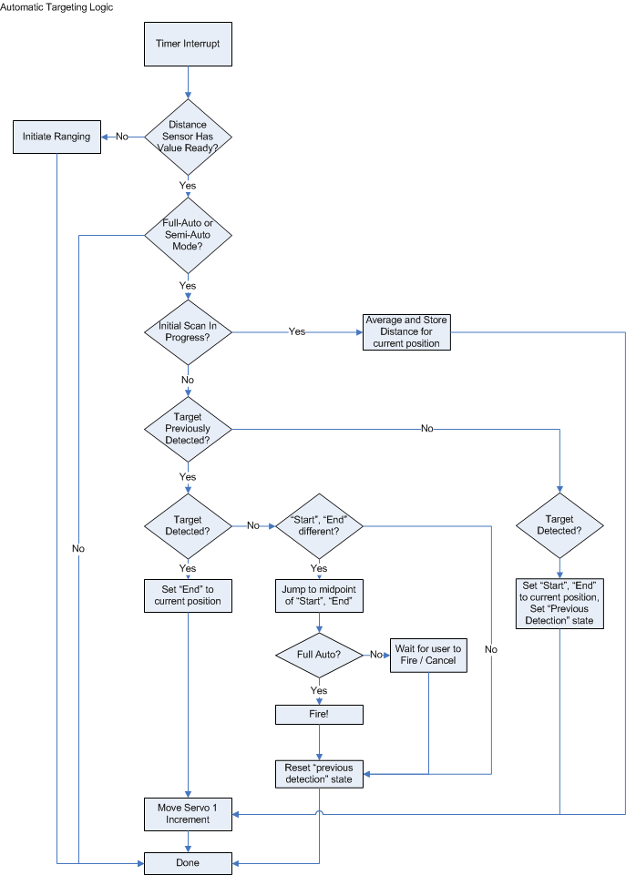
We used a timer to control the distance sensor, as it requires 65ms to return a value after ranging has been initiated (busy-waiting for this long would be unacceptable). All of our control logic for automatic targeting was also placed in this function. This function would be entered under two different situations; the first was when the code needed to trigger the distance sensor to get data and the second where data was ready on the distance sensor.
During the passes where data was ready there were two basic modes for the distance sensor code. The first mode was its pre-scanning mode where it built an initial "map" of the room, by completing four passes of the turret's full range of motion, and storing the averaged distance values for each position into an array. This initial scan would run automatically the first time semi or fully automatic mode was selected or, any time the "B" button on the controller was pressed.
The second mode for the distance sensor code was the targeting mode. This code basically checked to see if the current distance was less than the distance stored for the current position by the initial scanning procedure. If the returned distance was indeed shorter, this indicated a target, and the current position was then marked as the starting and ending position for the object. The next distance would then be checked, and if this position's distance was also closer than the distance stored in the array, the ending position of the target would be updated. This process would continue until a target was no longer indicated.
Once a target had been identified and a position found such that distance was no longer closer than the stored value (indicating the "end" of a target), the turret was positioned to the midpoint of the start and end distance. At this point, the user was notified that a target was ready, or the target was automatically shot - depending on the current mode.
In order to prevent false positives there were three major enhancements made in the code: First, as previously mentioned, the values of the four initial passes were averaged. Second, the distance sensor reading had to be at least two inches less than the stored value for a target to be "detected". Finally if a target was only identified at one position (the starting and ending position for the object were the same) that target was treated as a false positive and was ignored.
The Nintendo controller's associated FPGA hardware generated interrupts 60 times a second (i.e. every time the controller returned new data), regardless of what buttons were pressed. The handler code for this was used to control all manual user interaction with the turret. Because the interrupts occurred regardless of the controller's state, the software needed to remember state for the controller in order to determine when certain buttons were pressed.
Some logic did not require memory of preconditions: whenever the "A" button was held down, the solenoid was activated, causing the gun to fire (regardless of mode, though in semi-automatic mode, this action would also cancel target acquisition). Similarly, whenever the "Left" or "Right" buttons were held down, if the turret was in manual mode, the servo's position would increase or decrease, assuming it had not reached the limits of its range of motion. Also, if the "Up" button was pressed and the sensor had acquired a target in semi-automatic mode, the target acquisition would be cancelled.
However, the "select" button - to change mode - and the "B" button - to initiate scanning of the room - needed to detect when the user depressed the button, so that the resulting action would only be taken once, no matter how long the button was held down. As such, the end of the controller's interrupt routine stored the previous state of all the buttons for comparison by the next function execution.
The image sensor's FPGA hardware generated an interrupt every time a full frame was processed, at which point the software would read each segment's "red score" and determine which was greatest. The image sensor was disabled in the final design, for reasons that will be described below, so this information was not actually used. We did, however, construct a test in which the highest-scoring segment would be displayed on the BAR LED (see video).
Most of the major problems we encountered involved interfacing the image sensor to our design. Ultimately, it was determined that we could not successfully use the image sensor for target tracking without additional equipment:
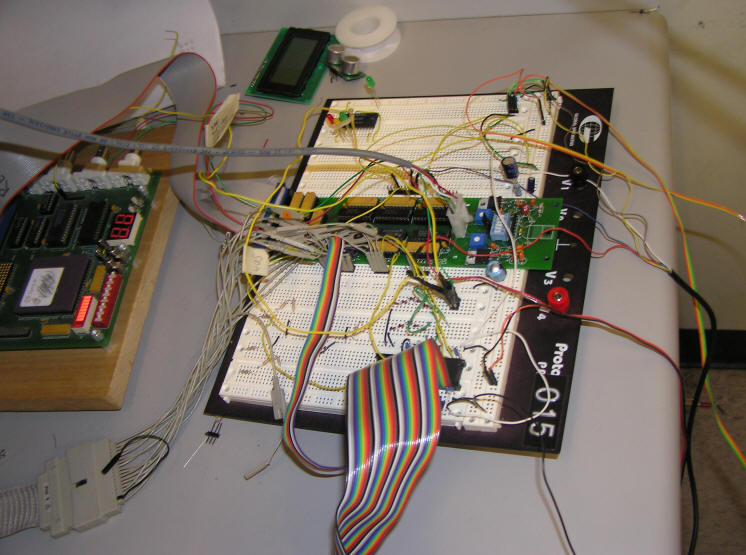
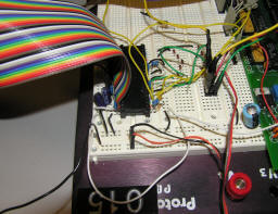
Our first hurdle was to connect to the I2C pins on the communication port provided by the MPC823's motherboard. In order to access the appropriate pins, we had to unscrew and lift up the MPC823's daughterboard and the board containing the FPGA. Naturally, we left these wires connected once they were in place.
We then realized that the image sensor ran on 3.3v signals, while our I/O board used 5v buffers. Most of the inputs and outputs to/from the sensor were unidirectional; for outputs, the I/O board's input buffers were simply tolerant of 3.3v levels, while for inputs, we used a simple voltage divider. The bidirectional I2C bus proved to be more of an issue, however we used a series of Zener diodes to clamp the levels on this bus down to 3.3v, and most other I2C devices we used were tolerant of the lowered voltage level.
Finally we ended up having some noise issues on a few of the signals to and from the image sensor especially the reset signal to the chip. This was a result of the capacitors being placed in the protoboard instead of the pcb for the image sensor. If we were to do this project again we would redesign the pcb and move the capacitors closer to the chip.
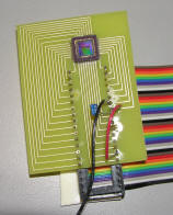
We did not have an appropriate lens for the image sensor, which rendered it useless for our intended purpose. Without a lens, its field of view was extremely narrow, and there was also a possibility that all the pixels were being over-exposed (a lens would have provided a limited aperture).
The logic we used for processing the data returned by the image sensor consumed 97% of the CLBs provided by the Xilinx XC4010E-PG191 FPGA, so we were unable to implement any additional controls or processing in the FPGA. In particular, this prevented us from following the recommended black-level calibration procedure described in Kodak's KAC-9647 Application Note 4, the lack of which might have had a detrimental effect on the accuracy of the data provided by the sensor. Furthermore, had we wanted to implement a more advanced image processing algorithm, this would have been impossible.
Additionally, we would have been greatly helped by having the ability to capture and later inspect a full frame from the sensor, but we did not have any devices capable of storing that much data (ie. the FPGA board had an 8 KB SRAM chip, but we would have needed something closer to 80KB even for a low-resolution frame, and still with a maximum access time below 100ns).
The ultrasonic distance sensor was not tolerant of the 3.3v I2C signals, so it and the image sensor were mutually exclusive. This did not turn out to be an issue, as the ultrasonic sensor was used as a replacement for the image sensor when it became clear that the image sensor could not be used as a sensing device without additional equipment.
Additionally, it occasionally failed to respond to I2C commands, causing the driver code to get stuck in an infinite loop. We didn't resolve this issue; we believe this may be because the reference voltage was closer to 4v than 5v, which may have been at the edge of the sensor's tolerance.
Finally, for the sensor to give accurate results, the target needed to be within a few feet.
One of the gears in the servo was missing a few teeth (it must've gotten into quite the brawl), so our range of motion was more limited than it might otherwise have been. We could not easily switch to a different servo because the others we tried had too little torque.
The Nintendo controller displayed some erratic behavior until we placed a clock buffer on the divided clock we used for the controller's latch/pulse generation.
The solenoid worked perfectly; it just required a dedicated power supply.
We occasionally ran out of space in our course directory, causing Xilinx to experience severe problems. A larger quota would be advisable for the future.
Overall our design was fairly successful. Our Nintendo controller, servo, and solenoid worked very well and preformed the functions required of them. Regrettably, we did have to make a last minute change, removing the image sensor in favor of a distance sensor. This reduced our range and also reduced our tracking ability.
In spite of our issues with the image sensor, we were able to perform some color tracking but only at a range of a few centimeters. In order to make image-sensor based tracking successful we needed a few different things: First and most importantly we really needed a lens that was specifically designed for our image sensor. We experimented with a few lenses from disposable film and digital cameras but were not able to get reasonable results. Additionally a larger FPGA is required: with our current FPGA, we had to simplify our algorithm and could not complete all of the desired processing. Finally, an invaluable tool when trying to use an image sensor would be to try to store an entire picture from the image sensor; this would provide a better idea of what the sensor is "seeing", and what settings should be changed to get better results.
In the end, we had a Nerf turret which was fully functional in "manual" mode, and was capable of some target detection at a reasonably close range. In addition, we believe we set a strong foundation for working with image sensors; were we to approach this project again, and with the right equipment, we would be successful.